01
Phased-array synthesis
Configure the aperture, element spacing and excitation phases. Explore steering and inspect the phase map alongside the resulting radiation pattern.
A clear XZ section through the recorded electric field.
2D field section · expanded air domainA clean section through the horn and the surrounding air.
2D field section · expanded air domainA recorded field section above the original 2 × 2 array.
2D Ez section · projected CAD footprintOriginal software views and exported simulation results, with a dedicated page for each example.
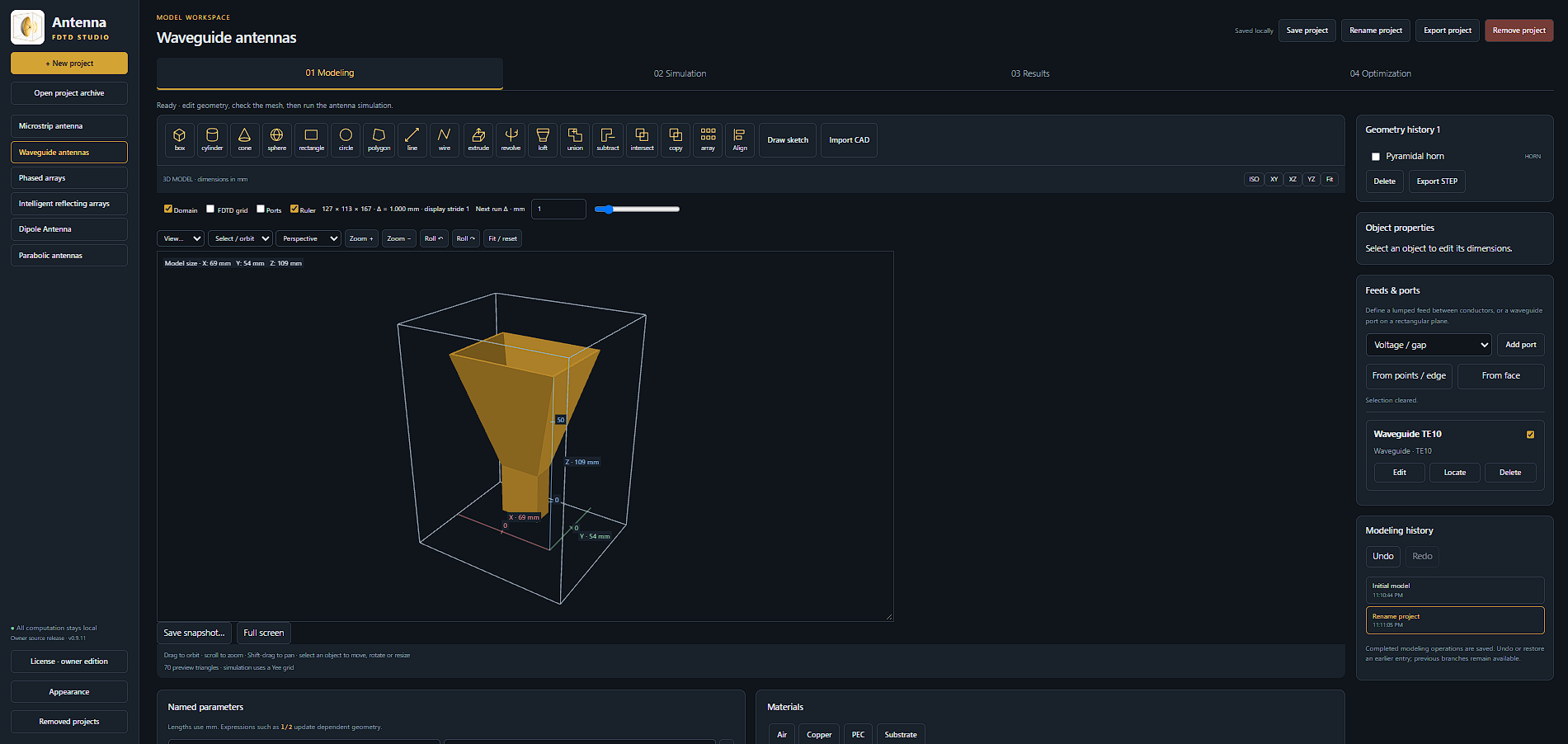
Model setup, recorded fields, radiation patterns and port response.
Explore the example ↗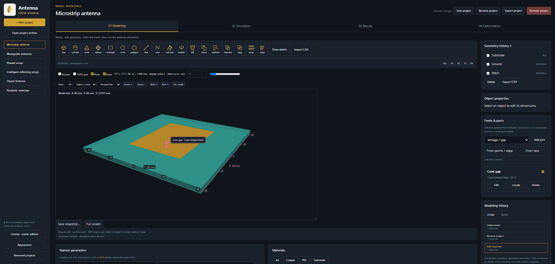
Model setup, recorded fields, radiation patterns and port response.
Explore the example ↗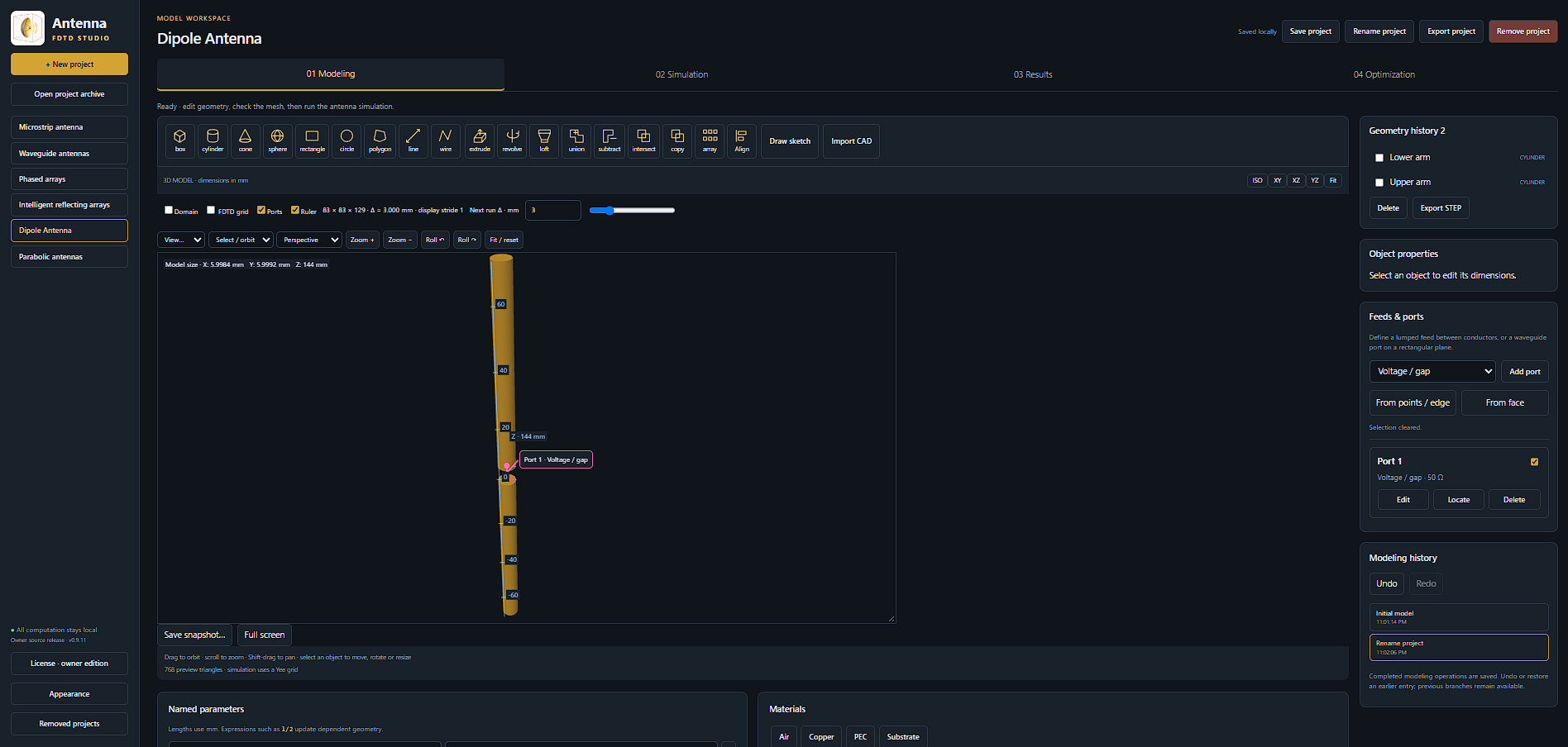
Model setup, recorded fields, radiation patterns and port response.
Explore the example ↗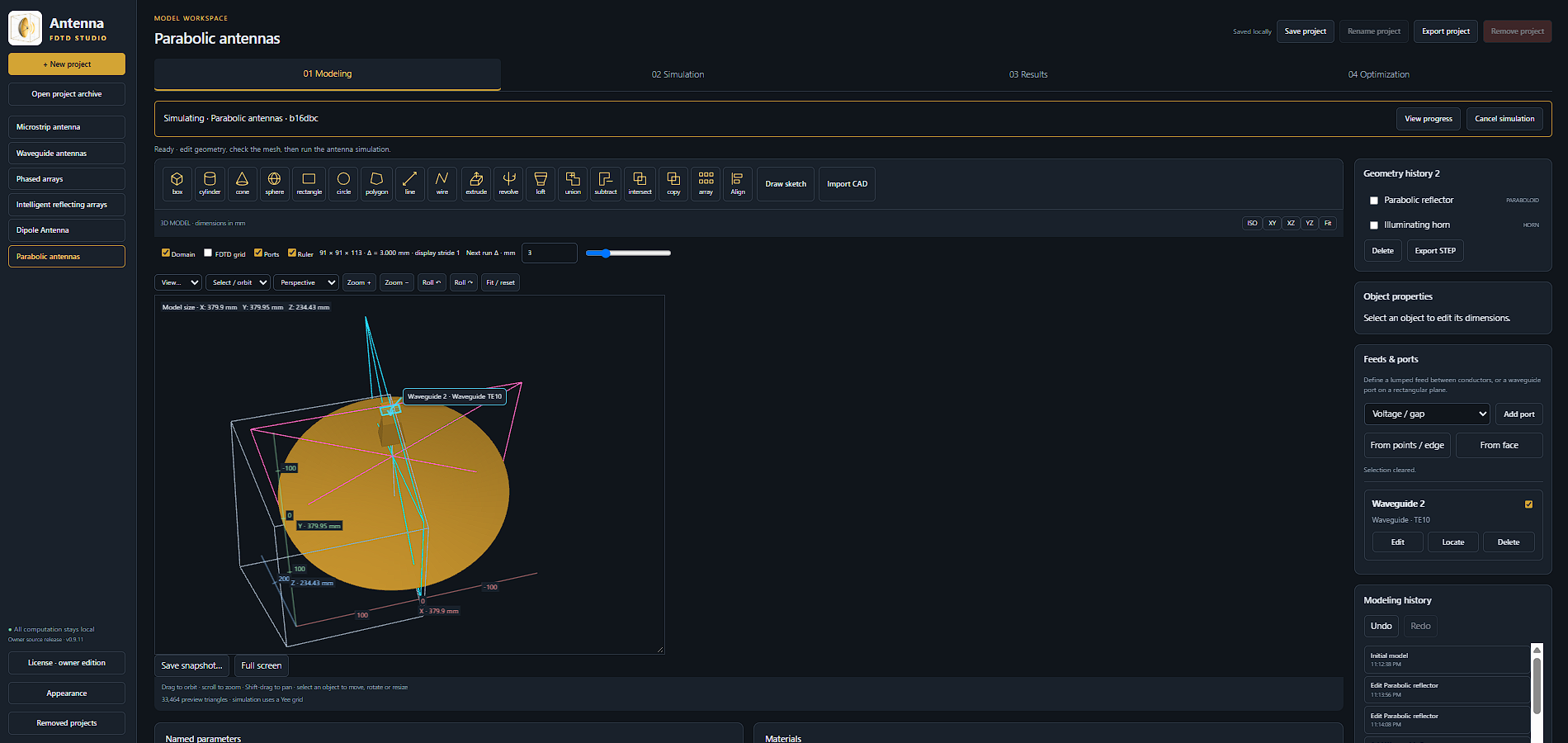
Reflector and feed setup, recorded fields, radiation patterns and port response.
Explore the example ↗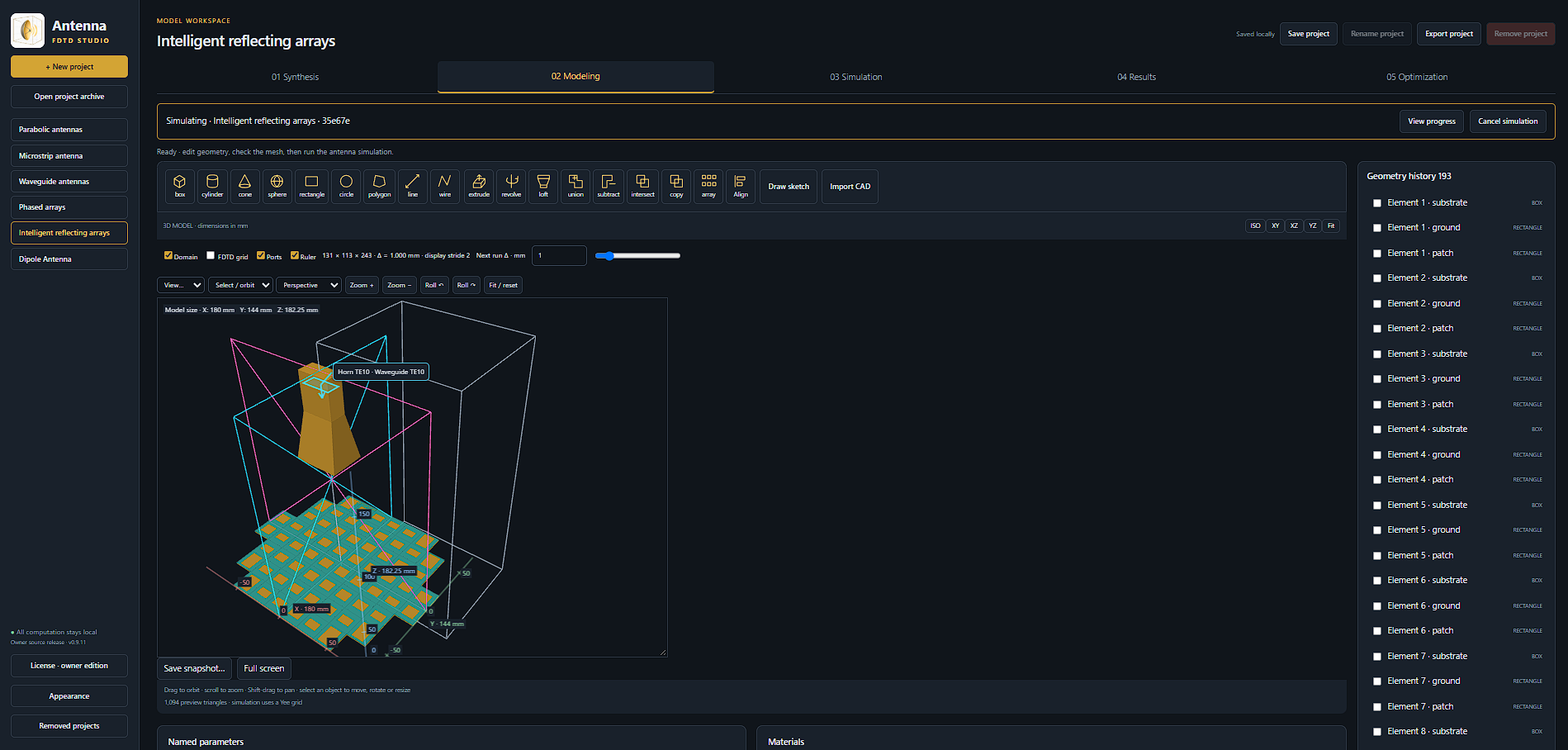
Phase synthesis, array geometry, radiation patterns and recorded frequency response.
Explore the example ↗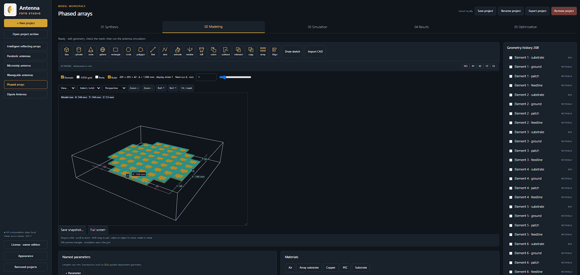
Array synthesis, geometry, recorded fields, radiation patterns and port response.
Explore the example ↗Explore beam steering, phase distributions and reflectarray phase-to-geometry synthesis, including height-profile apertures beyond a flat surface.
Conformal height profiles use stepped planar tiles. Unit-cell phase calibration and full-array behavior require separate validation.
Configure the aperture, element spacing and excitation phases. Explore steering and inspect the phase map alongside the resulting radiation pattern.
Investigate return loss and compare how design changes affect the antenna response.
Explore radiation patterns to understand beam direction, coverage and sidelobe behavior.
Map reflection phase to patch dimensions and configure element heights to explore non-flat apertures. Inspect the phase error and validate the assembled array response.
Tell us about your geometry, frequency range and the results you need. Start a conversation about Antenna FDTD Studio and a suitable demonstration.
These are recorded outputs from the original Antenna FDTD Studio 3D solver, shown as clear signed-component sections through the recorded 3D fields with the actual CAD geometry. Dipole and horn air domains are expanded; the array outline is a projected CAD footprint over near-surface field sections. Each example has 192 recorded time samples. Domain guides are hidden and field edges fade visually; no fields are invented outside the recorded domain. Scalar fields are interpolated and colorized during playback, with contour lines and a separate high-resolution CAD layer. The array uses simultaneous excitation and reports active reflection, not a full S-matrix.